The following is a guide to good Sintered Metal (P/M) Design. We are Presenting the efficient and economical Designs from our manufacturing perspective. Specific features and requirements which cannot be directly accomplished in the basic process can always be added by the secondary machining operation.
Exceptions will arise due to the size, density and application of a part. For that reason, we encourage you to consult with our technical staff at any time.
1. Metal powders are worked cold and in a solid phase. Therefore:
• During pressing, the powder will not flow around corners.
• During pressing, the powder will not compact in blind recesses.
• Density in different sections of fill may be different. Those gradients may cause stress and subsequent warpage.
2. High pressure 120-45 tons/sq. inch) is employed in pressing. Therefore, tooling should have sections rigid enough to withstand this pressure.
3. As a fully-enclosed die cavity is used and the lower punch ejects the compact, a smooth die wall in the direction of ejection is required.
4. Die cavities are filled with powder to a volume of approximately 2-V2 times the finished volume. Because of that compression ratio, each level of a part requires an independent level of powder fill.
5. while sintering temperatures are generally below the melting point of the base metal, some dimensional distortion may occur.
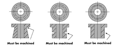
1. We need a smoother die wall for ejection. Reverse angles undercut, and threads cannot be moulded but may be finished by secondary operations
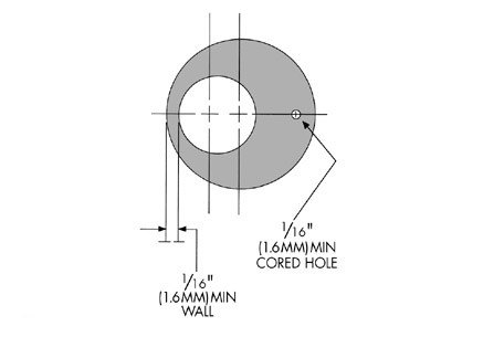
2. Thin walls and small holes require thin sections on punches and thin core rods. For durable, sturdy tooling, keep walls to 1/16” (1.575)min. and cored holes to 1/16” (1.575)min.
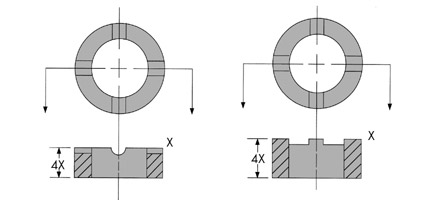
3. Large, thin sections attached to long hubs are difficult to eject from multiple levels die. Cracks, stress, and density gradients may develop between the two sections. (a) Make large projections as thick as possible. (b) Add radii under the shoulder to aid in an injection. (c) Eliminate sharp edges on punches by radius.
4. Details may be ‘plunged,’ i.e., pressed by the top punch, to 25% of the total length of a part. A bullet nose or rounded projection on the punch aids in equalizing density. Conversely, male projections may be moulded to 25% of the total length. A 1o draft helps in releasing the top punch from the compact.
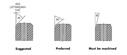
5. To reduce the effect of burrs and to break sharp corners, it is good practice to chamfer edges of parts. An angle greater than 45o is suggested, but chamfers less that 30o would have to be added as a secondary operation. To eliminate a feather edge on a punch, a flat of .005″(.127)min. is added to the end of the chamfer.
6. Length should be no greater than 2-1/2 times diameter and no greater than 10times wall thickness.
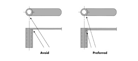
7. Avoid vertical radii on the edges of parts to eliminate feather edges on punches. the prefered design would be two chamfers; however, keep chamfer edges as far apart as possible to eliminate breakage.
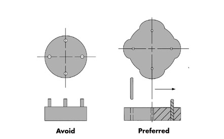
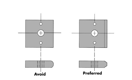
8. Abrupt changes in the cross section should be avoided, as density changes and die ejection problems will result. In the application shown, holes are cored and taper pins are assembled therein. Note the increase in wall section for sturdier tooling.
Innovation House, Fleet Lane, St Helens, WA9 2RJ